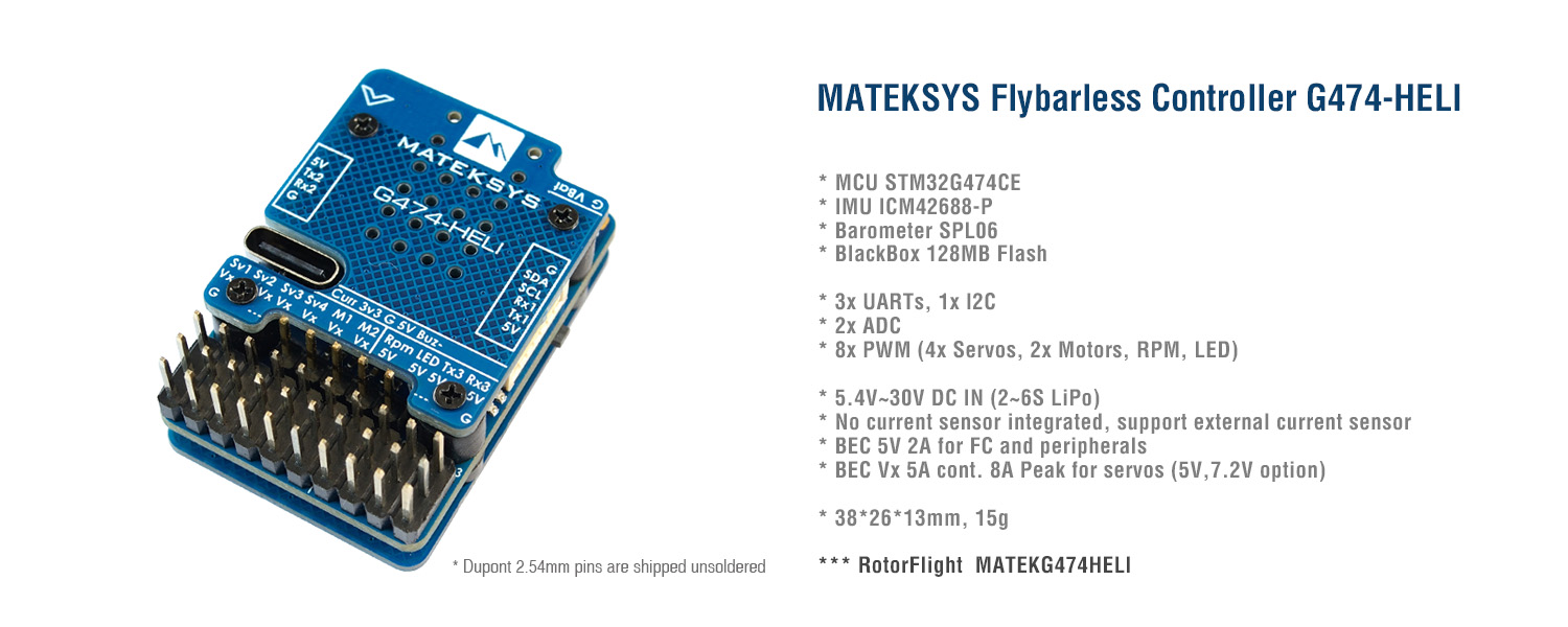
RC Helicopter Flybarless Controller G474-HELI
STM32G474, ICM42688P, SPL06L, 2x BEC, Rotorflight firmware
Tips
Download “MATEKG474HELI” target fw directly in configurator and flash.
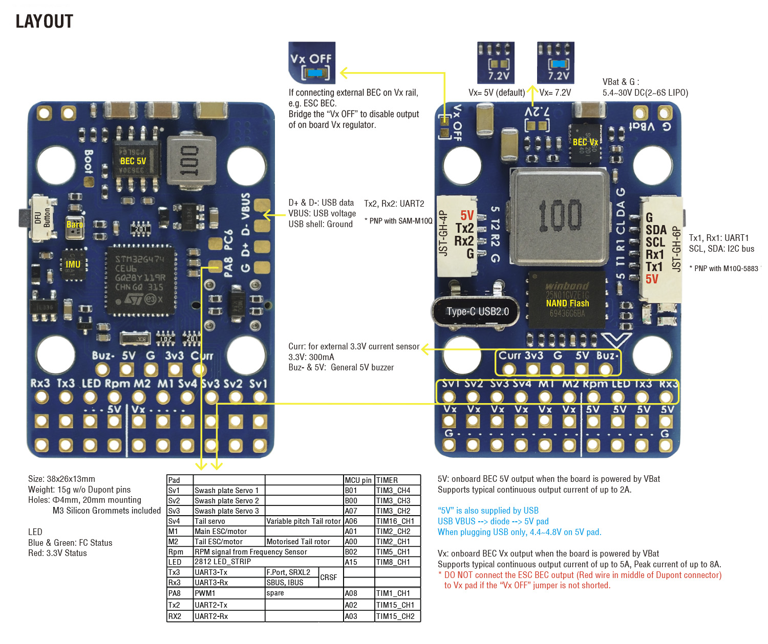
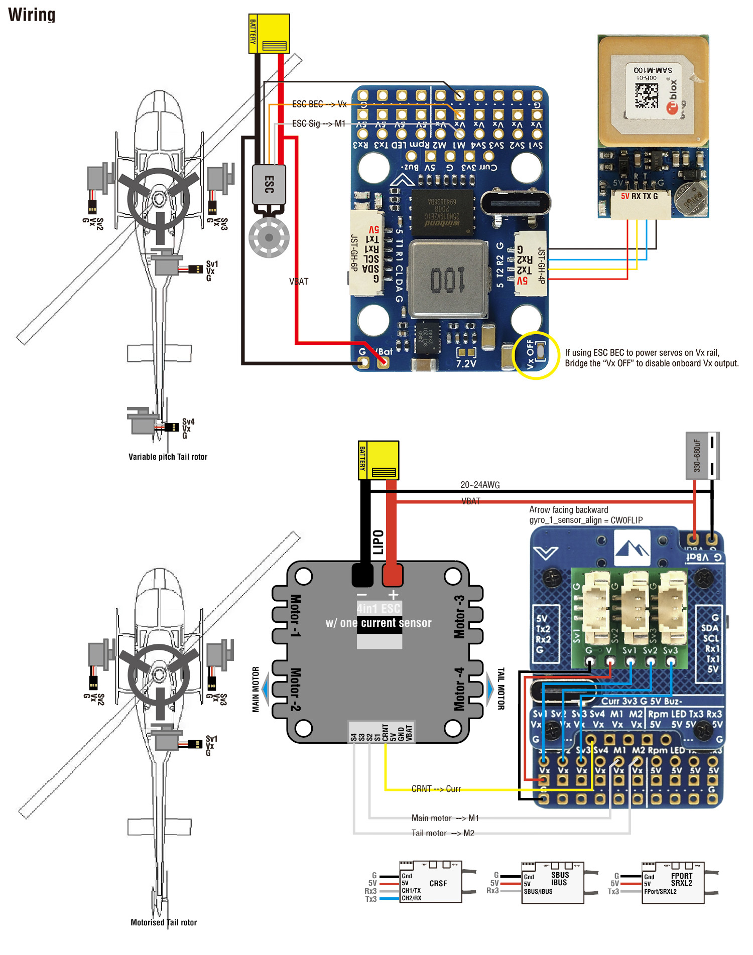
If you don’t use the onboard Vx regulator, bridge “Vx OFF”, but the 5V regulator on FC board still need to be powered from “VBat and G”. If you want the wiring simpler, G474-HLite is designed to be powered from Vx rail.
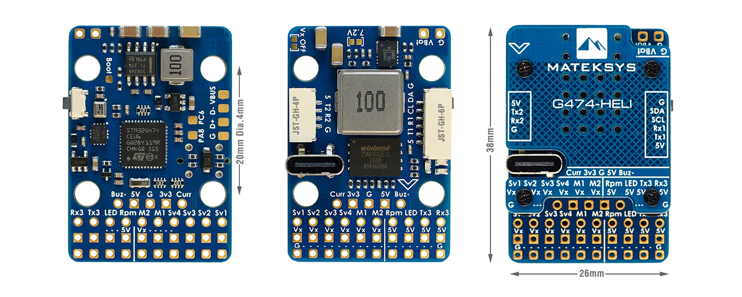
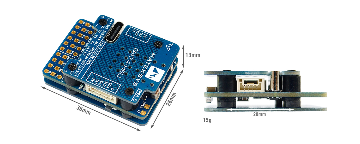
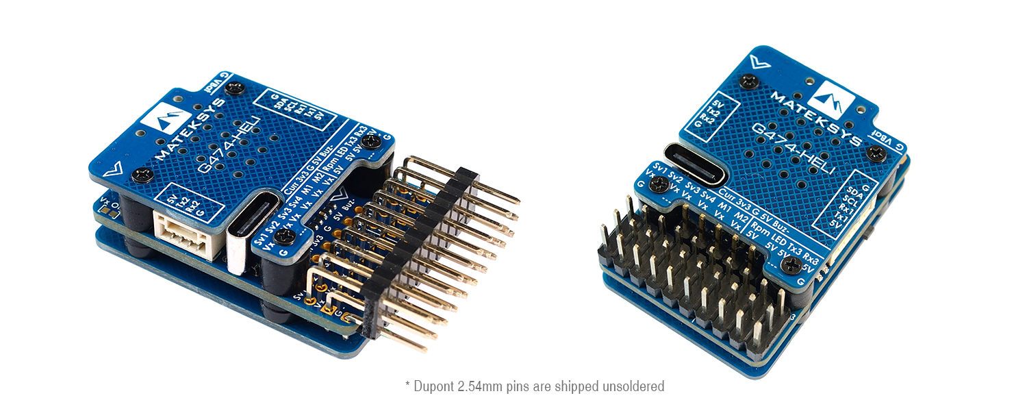
Specifications
- MCU: STM32G474CE, 170MHz Cortex-M4 , 512KB Flash
- IMU: ICM42688-P
- Baro: SPL06
- Blackbox: 128MB Flash (1G-bit NAND)
- 3x UARTs (1, 2, 3)
- 1x I2C
- 8x PWM (4x Servos, 2x Motors, RPM, LED)
- 2x ADC (VBAT, Current)
- USB Type-C(USB2.0)
Electrical characteristics
- Input voltage range: 5.4V~30V (2~6S LiPo)
- No current sensor integrated, support external 3.3V based current sensor.
- Battery Voltage divider 1K:10K (Scale 110)
- BEC 5V 2A for FC and peripherals
- BEC Vx 5A cont. 8A Peak for servos (5V, 7.2V option)
- 3.3V 300mA
Firmware/config
- Rotorflight / MATEKG474HELI
Physical
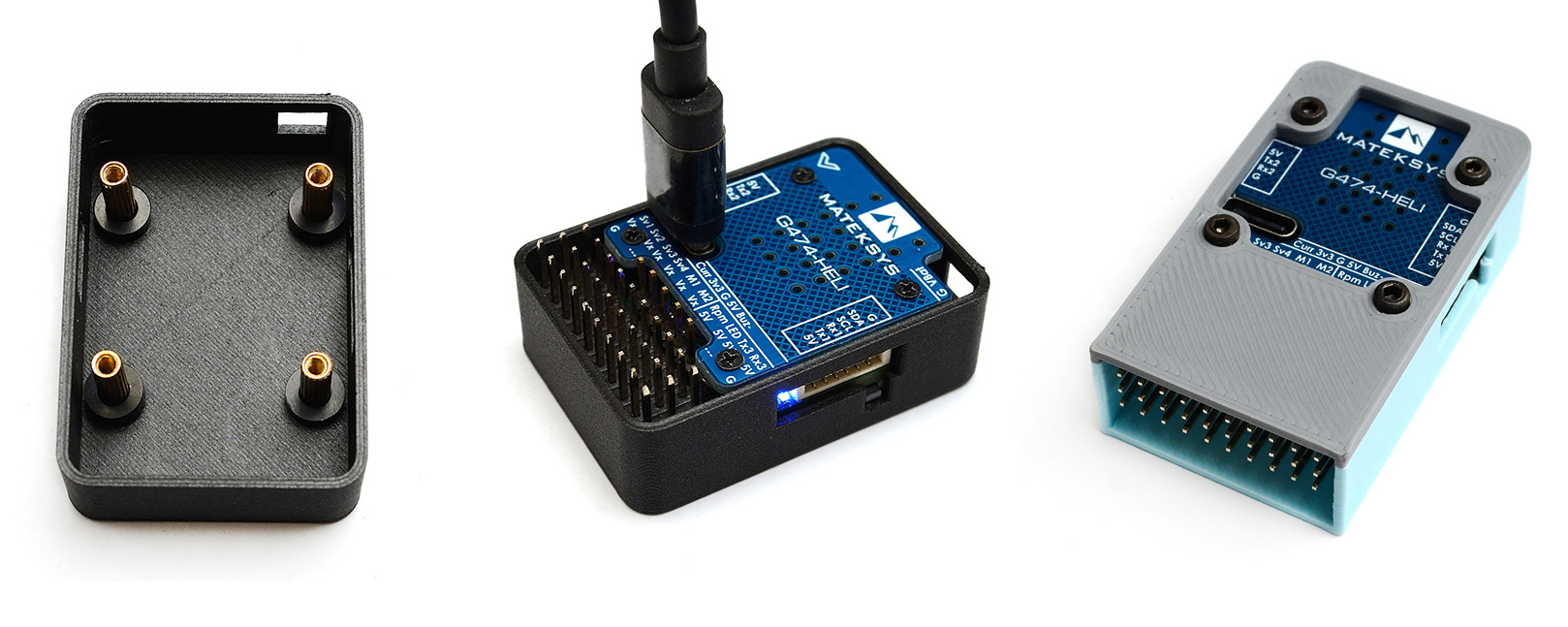
- Mounting: 20 x 20mm, Φ4mm with Grommets Φ3mm
- Dimensions: 38 x 26 x 13 mm
- Weight: 15g (w/o pins)
- 3D step file
Including
- 1x G474-HELI
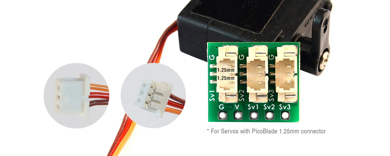
- 1x PicoBlade 1.25mm Servo adapter (M2/S2 servos)
- 1x 20cm JST-GH-4P to JST-GH-4P cable
- 1x 20cm JST-GH-6P to JST-GH-6P cable
- Dupont 2.54 pins (Board is shipped unsoldered)
- Swashplate Servo Numbering RF Wiki
- Rotorflight configurator 2.x https://github.com/rotorflight/rotorflight-configurator/releases
- Rotorflight Wiki https://github.com/rotorflight/rotorflight/wiki
Flahing firmware
- [Firmware preloaded in factory] rotorflight_4.3.0_MATEKG474HELI.hex (built from RF2 devel branch of Nov.1). Load firmware (local) –> Flash firmware.
- [Flashing with latest RF2 fw] Select “MATEKG474HELI” target in Rotorflight configurator –> Load firmware (online) –> Flash firmware.
- [Flashing with latest RF2 fw] Select “STM32G47X” target in Rotorflight configurator –> Load firmware (online) –> Flash firmware. After flashing and G474-HELI rebooting, connect G474-HELI to RF configurator, go into CLI mode, copy and paste all config lines into CLI, type “save”, press ENTER.
- MATEKG474HELI.config
board_name MATEKG474HELI
manufacturer_id MTKS
# resources
resource BEEPER 1 B09
resource MOTOR 1 A01
resource MOTOR 2 A00
resource SERVO 1 B01
resource SERVO 2 B00
resource SERVO 3 A07
resource SERVO 4 A06
resource FREQ 1 B02
resource PWM 1 A08
resource LED_STRIP 1 A15
resource SERIAL_TX 1 A09
resource SERIAL_TX 2 A02
resource SERIAL_TX 3 B10
resource SERIAL_TX 4 C10
resource SERIAL_RX 1 A10
resource SERIAL_RX 2 A03
resource SERIAL_RX 3 B11
resource SERIAL_RX 4 C11
resource I2C_SCL 1 A13
resource I2C_SDA 1 A14
resource LED 1 C14
resource LED 2 C15
resource SPI_SCK 1 B03
resource SPI_SCK 2 B13
resource SPI_MISO 1 B04
resource SPI_MISO 2 B14
resource SPI_MOSI 1 B05
resource SPI_MOSI 2 B15
resource ADC_BATT 1 A04
resource ADC_CURR 1 A05
resource FLASH_CS 1 B12
resource GYRO_EXTI 1 B07
resource GYRO_CS 1 B06
# timer
timer B01 AF2
# pin B01: TIM3 CH4 (AF2)
timer B00 AF2
# pin B00: TIM3 CH3 (AF2)
timer A07 AF2
# pin A07: TIM3 CH2 (AF2)
timer A06 AF1
# pin A06: TIM16 CH1 (AF1)
timer A01 AF1
# pin A01: TIM2 CH2 (AF1)
timer A00 AF1
# pin A00: TIM2 CH1 (AF1)
timer B02 AF2
# pin B02: TIM5 CH1 (AF2)
timer A08 AF6
# pin A08: TIM1 CH1 (AF6)
timer A15 AF2
# pin A15: TIM8 CH1 (AF2)
timer B09 AF1
# pin B09: TIM17 CH1 (AF1)
timer A02 AF9
# pin A02: TIM15 CH1 (AF9)
timer A03 AF9
# pin A03: TIM15 CH2 (AF9)
# dma
dma ADC 1 10
# ADC 1: DMA2 Channel 3 Request 5
dma ADC 2 11
# ADC 2: DMA2 Channel 4 Request 36
dma pin B01 0
# pin B01: DMA1 Channel 1 Request 64
dma pin B00 1
# pin B00: DMA1 Channel 2 Request 63
dma pin A07 2
# pin A07: DMA1 Channel 3 Request 62
dma pin A06 3
# pin A06: DMA1 Channel 4 Request 82
dma pin A01 4
# pin A01: DMA1 Channel 5 Request 57
dma pin A00 5
# pin A00: DMA1 Channel 6 Request 56
dma pin B02 6
# pin B02: DMA1 Channel 7 Request 72
dma pin A08 7
# pin A08: DMA1 Channel 8 Request 42
dma pin A15 8
# pin A15: DMA2 Channel 1 Request 49
# feature
feature RX_SERIAL
feature TELEMETRY
feature LED_STRIP
# serial
serial 2 64 115200 57600 0 115200
# master
set battery_meter = ADC
set current_meter = ADC
set vbat_scale = 110
set beeper_inversion = ON
set beeper_od = OFF
set beeper_frequency = 2500
set system_hse_mhz = 8
set gyro_1_bustype = SPI
set gyro_1_spibus = 1
set gyro_1_sensor_align = CW180FLIP
set mag_hardware = AUTO
set mag_bustype = I2C
set mag_i2c_device = 1
set baro_hardware = AUTO
set baro_bustype = I2C
set baro_i2c_device = 1
set flash_spi_bus = 2
set blackbox_device = SPIFLASH
set serialrx_provider = CRSF
set dshot_burst = OFF
save
Blheli bi-direction Dshot ESC, enabled RPM filter: feature rpm_filter
Tips
- If GPS, Receiver or other peripherals are connected to UART2(Tx2,Rx2) and these peripherals are powered ON while connecting USB. STM32G474 will not go into DFU mode. It is related to DFU protocol used in the STM32G474 bootloader. Pls unplug peripherals from UART2 before you try flashing the FC.
- There is no UART4 breakout on this board.
- If using Frsky SBUS+SmartPort receivers. you may remap one of PWM pins to softserial_tx for SmartPort, e.g. LED pin, resource serial_tx 11 A15 , feature softserial .
- You can also resource LED pin to RX2 for ESC telemetry, ” resource LED_STRIP 1 none, resource SERIAL_RX 2 A15 “
- Due to leakage voltage on MCU I/O, there is floating current readout when no external current sensor connected. If you don’t use external current sensor. set current_meter = NONE .
- If the FC is mounted with arrow facing backward. set gyro_1_sensor_align = CW0FLIP
- Blheli bi-direction Dshot ESC, enabled RPM filter: feature rpm_filter
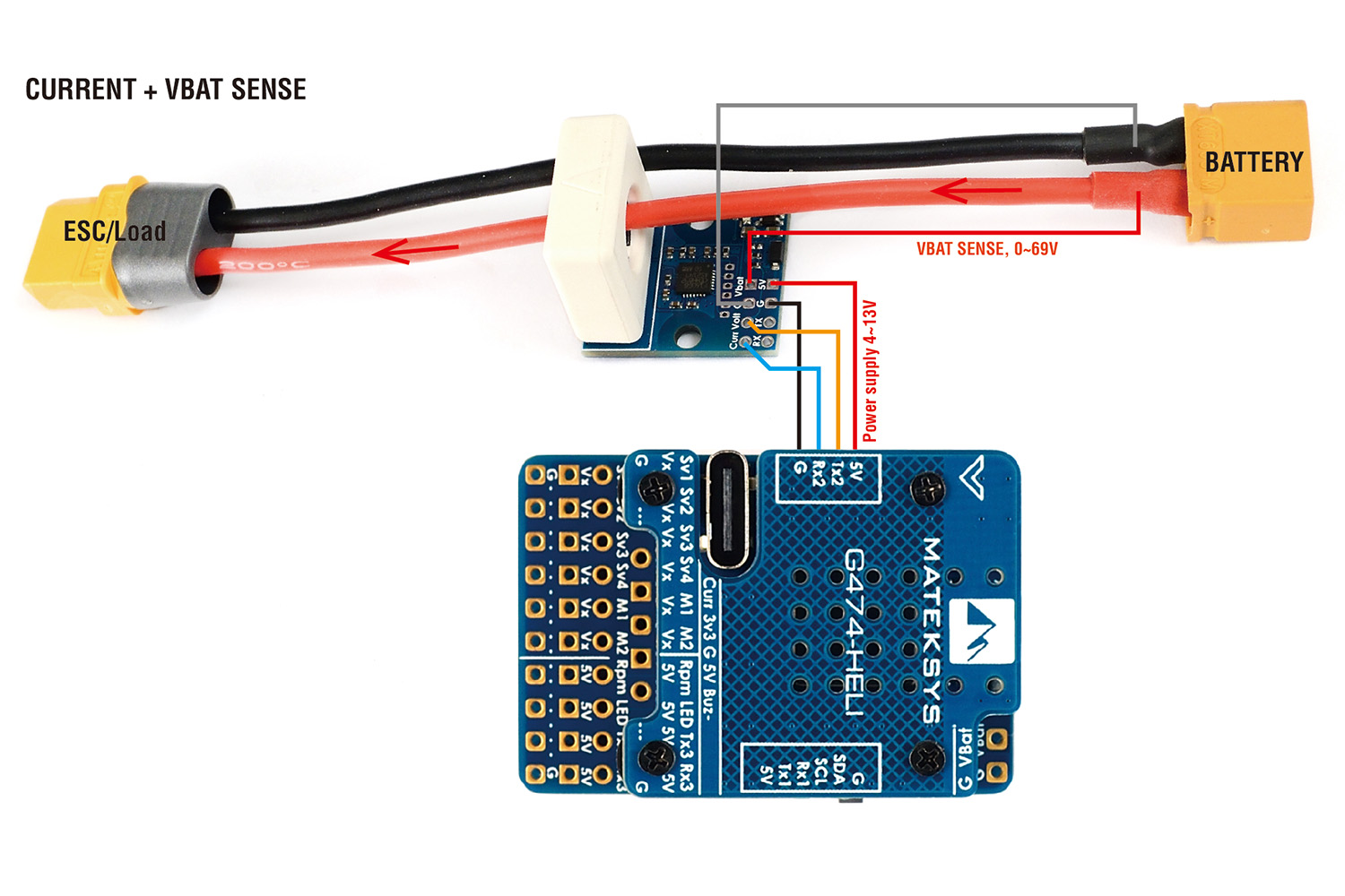
CLI command
- resource SERIAL_RX 2 none
- resource ADC_CURR 1 A03
- set ibata_scale = 200
- resource SERIAL_TX 2 none
- resource ADC_BATT 1 A02
- set vbat_scale = 210

