Flight Controller F405-WMO
STM32F405RGT6, ICM42688P, SPL06, OSD, SD slor, 4xUARTs, 9x PWM,1xI2C, 2xADC

Gallery
Spec.& Manual
F405-WMO Quick Start Guide PDF
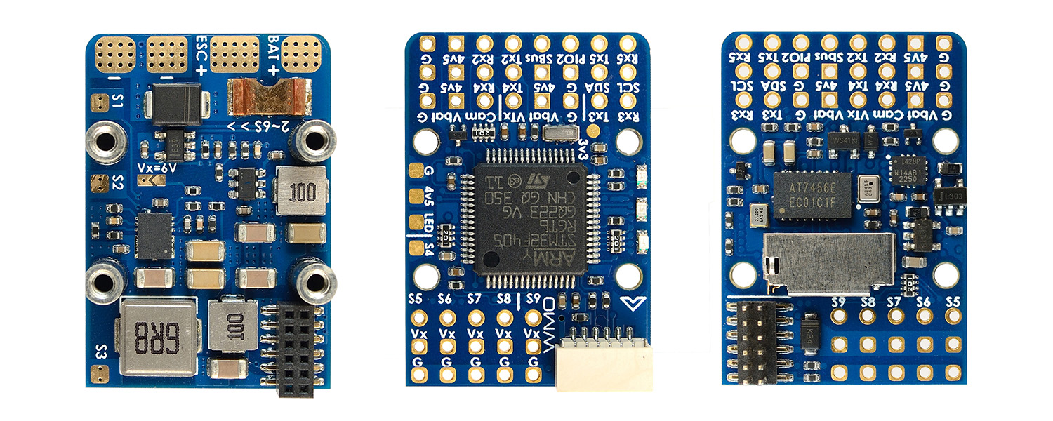
FC Specifications
- MCU: STM32F405RGT6, 168MHz , 1MB Flash
- IMU: ICM42688-P
- Baro: SPL06-001
- OSD: AT7456E
- Blackbox: SD card slot
- 4x UARTs
- 10x PWM outputs
- 1x I2C
- 2x ADC (VBAT, Current)
- 1x spare PINIO
- Vbat output ON/OFF control
- USB/Beep Extender with Type-C(USB2.0)
- Built in inverter on UART2-RX for SBUS input
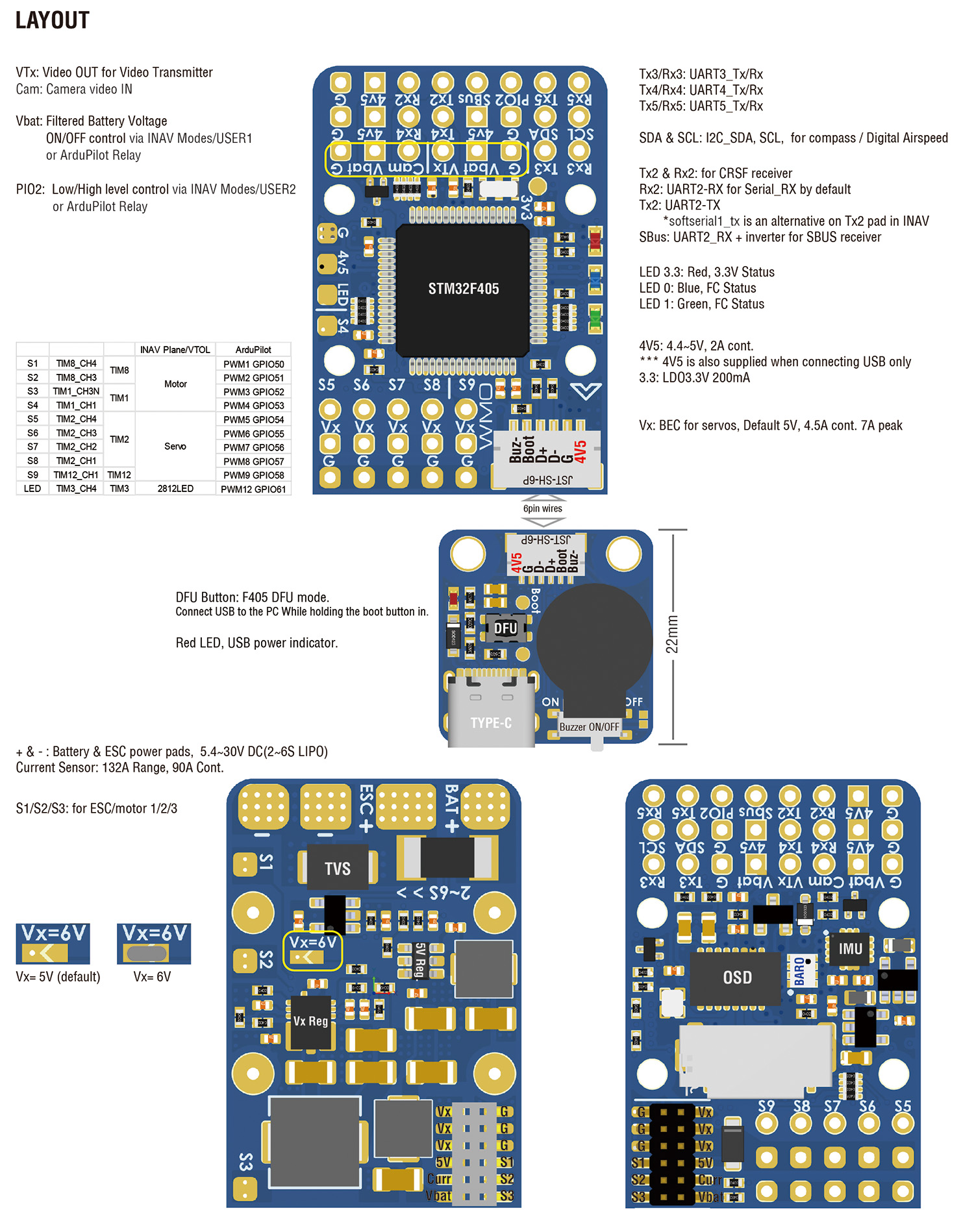
Power
- 5.4~30V DC IN (2~6S LiPo)
- 132A Current Sense (INAV Scale 250, ArduPilot 40A/V)
- PDB/Current sense resistor: 90A continuous, 132A burst.
- BEC 5V(4v5) 2A for FC & Peripherals
- BEC Vx 4.5A cont.(7A peak) for servos, 5V/ 6V option
- Filtered Vbat for VTX and camera
- LDO 3.3V 200mA
- Battery Voltage Sensor: 1k:20k
FC Firmware
- ArduPilot: MatekF405-TE
- INAV: MATEKF405TE_SD
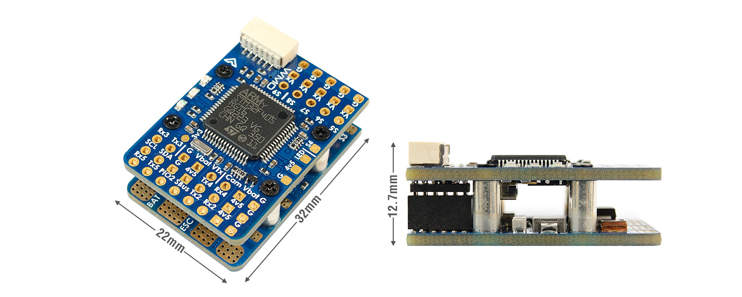
Physical
- Dimensions: 32 x 22 x 12.7 mm
- Weight: 9g
Including
- 1x F405-WMO
- 1x USB(Type-C)/Beep (Passive buzzer) Extender + 20cm JST-SH-6P cable for USB extender.
- Dupont 2.54 pins (Board is shipped unsoldered)
Layout
Wiring
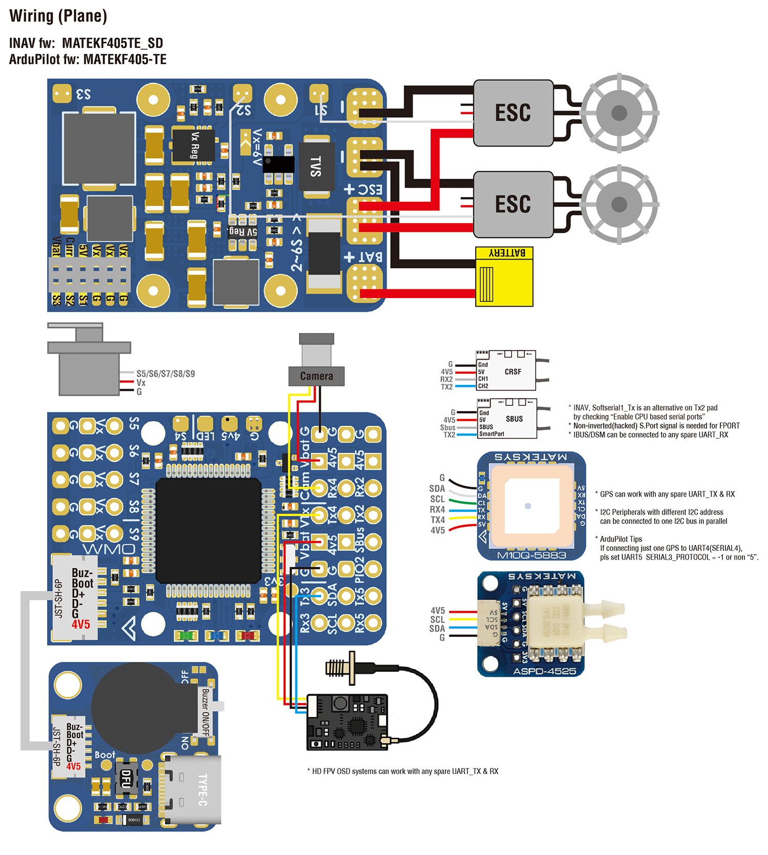
INAV mapping
| INAV | TIM | INAV Plane/VTOL | |||
| PWM | S1 | 5 V tolerant I/O | TIM8_CH4 | TIM8 | Motor |
| S2 | 5 V tolerant I/O | TIM8_CH3 | |||
| S3 | 5 V tolerant I/O | TIM1_CH3N | TIM1 | ||
| S4 | 5 V tolerant I/O | TIM1_CH1 | |||
| S5 | 5 V tolerant I/O | TIM2_CH4 | TIM2 | Servo | |
| S6 | 5 V tolerant I/O | TIM2_CH3 | |||
| S7 | 5 V tolerant I/O | TIM2_CH2 | |||
| S8 | 5 V tolerant I/O | TIM2_CH1 | |||
| S9 | 5 V tolerant I/O | TIM12_CH1 | TIM12 | ||
| LED | 5 V tolerant I/O | TIM3_CH4 | TIM3 | 2812LED | |
| ADC | Vbat voltage | 5.4~30V | ADC_CHANNEL_1 | voltage scale 2100 | |
| Current | 0~3.3V | ADC_CHANNEL_2 | current scale 250 | ||
| I2C | SCL SDA |
5V tolerant I/O | Compass | ||
| OLED | |||||
| onboard Barometer | |||||
| Digital Airspeed sensor | |||||
| Temperature sensor | |||||
| UART | USB | 5V tolerant I/O | USB | ||
| TX3 RX3 | UART3 | USER | |||
| TX4 RX4 | UART4 | USER | |||
| TX5 RX5 | UART5 | USER | |||
| TX2 RX2 | TX2 & RX2 | CRSF | |||
| SBus pad | for SBUS receiver, SBus pad = RX2+inverter | ||||
| RX2 pad | IBUS/DSM | ||||
| TX2 pad | SRXL2 | ||||
| TX2 pad | FPORT, uninverted S.Port/F.Port signal (hacked) | ||||
| TX2 pad | SmartPort Telemetry | enable Softserial_Tx1 | |||
ArduPilot mapping
| ArduPilot | |||||
| PWM 5V tolerant I/O |
S1 | PWM1 GPIO50 | TIM8_CH4 | DMA/DShot | Group1 |
| S2 | PWM2 GPIO51 | TIM8_CH3 | DMA/DShot | ||
| S3 | PWM3 GPIO52 | TIM1_CH3N | DMA/DShot | Group2 | |
| S4 | PWM4 GPIO53 | TIM1_CH1 | DMA/DShot | ||
| S5 | PWM5 GPIO54 | TIM2_CH4 | DMA/DShot | Gourp3 | |
| S6 | PWM6 GPIO55 | TIM2_CH3 | DMA/DShot | ||
| S7 | PWM7 GPIO56 | TIM2_CH2 | DMA/DShot | ||
| S8 | PWM8 GPIO57 | TIM2_CH1 | DMA/DShot | ||
| S9 | PWM9 GPIO58 | TIM12_CH1 | NO DMA | Gourp4 | |
| LED pad | PWM12 GPIO61 | TIM3_CH4 | DMA/DShot | Gourp5 | |
| SERVO12_FUNCTION 120, NTF_LED_TYPES neopixel | |||||
| Mixing Dshot and normal PWM operation for outputs is restricted into groups, ie. enabling Dshot for an output in a group requires that ALL outputs in that group be configured and used as Dshot, rather than PWM outputs. If servo and motor are mixed in same group, make sure this group run lowest PWM frequency according to the servo specification. ie. Servo supports Max. 50Hz, ESC must run at 50Hz in this group. |
|||||
| ADC | Vbat sensor | 0~30V | 1K:20K divider builtin | BATT_VOLT_PIN BATT_VOLT_MULT |
14 21.0 |
| Current sensor | 0~3.3V | onboard current sense | BATT_CURR_PIN BATT_AMP_PERVLT |
15 40 |
|
| I2C | I2C1 | 5V tolerant I/O | Compass | COMPASS_AUTODEC | 1 |
| onboard Baro SPL06-001 | Address | 0x76 | |||
| Digital Airspeed I2C MS4525 DLVR-L10D |
ARSPD_BUS ARSPD_TYPE ARSPD_TYPE |
1 1 9 |
|||
| UART 5V tolerant I/O |
USB | USB | console | SERIAL0 | |
| TX3 RX3 | USART3 | NO DMA | telem2 | SERIAL2 | |
| TX5 RX5 | UART5 | NO DMA | GPS1 *** | SERIAL3 | |
| TX4 RX4 | UART4 | NO DMA | GPS2 *** | SERIAL4 | |
| TX2 RX2 SBUS |
USART2 | with DMA | RC input/Receiver | SERIAL6 | |
| RX2 | IBUS/DSM/PPM | BRD_ALT_CONFIG 0 Default |
|||
| Sbus pad | SBUS | ||||
| TX2 & RX2 | CRSF | BRD_ALT_CONFIG 1 SERIAL6_PROTOCOL 23 |
SERIAL6_OPTIONS 0 | ||
| TX2 | uninverted FPort (hacked) | SERIAL6_OPTIONS 4 | |||
| TX2 | SRXL2 | SERIAL6_OPTIONS 4 | |||
- *** If connecting just one GPS to UART4(TX4/RX4), pls set SERIAL3_PROTOCOL = -1 or non “5”. otherwise ArduPilot will stop searching for GPS during bootup if not found on the first port(SERIAL3/UART5) configured for GPS protocol.
SD card logging
- set LOG_BACKEND_TYPE = 1 (File)
Frsky Smartport Telemetry
- non-inverted (hacked) S.Port signal
- any spare Uart_TX
- SERIALx_BAUD 57
- SERIALx_OPTIONS 7
- SERIALx_PROTOCOL 4 or 10(for yaapu)
Relay(PINIO)
- PINIO1, Vbat output ON/OFF, ON by default
- PINIO2, PIO2 pad output Low/High Level, Low Level by default
# GPIOs
- PA4 PINIO1 OUTPUT GPIO(81) LOW
- PB5 PINIO2 OUTPUT GPIO(82) LOW
# RCx_OPTION: RC input option
- 28 Relay1 On/Off
- 34 Relay2 On/Off
e.g.
- RELAY1_FUNCTION 1
- RELAY1_PIN 81
- RC7_OPTION 28 //Use CH7 of Transmitter to control Vbat output ON/OFF
- RELAY2_FUNCTION 1
- RELAY_PIN2 82 //PIO2 pad
- RC8_OPTION 34 //Use CH8 of Transmitter to control PIO2 Low/High Level
The configured feature will be triggered when the auxiliary switch’s pwm value becomes higher than 1800. It will be deactivated when the value falls below 1200.
Check the pwm value sent from the transmitter when the switch is high and low using the Mission Planner’s Initial Setup >> Mandatory Hardware >> Radio Calibration screen. If it does not climb higher than 1800 or lower than 1200, it is best to adjust the servo end points in the transmitter.
Difference from WMN
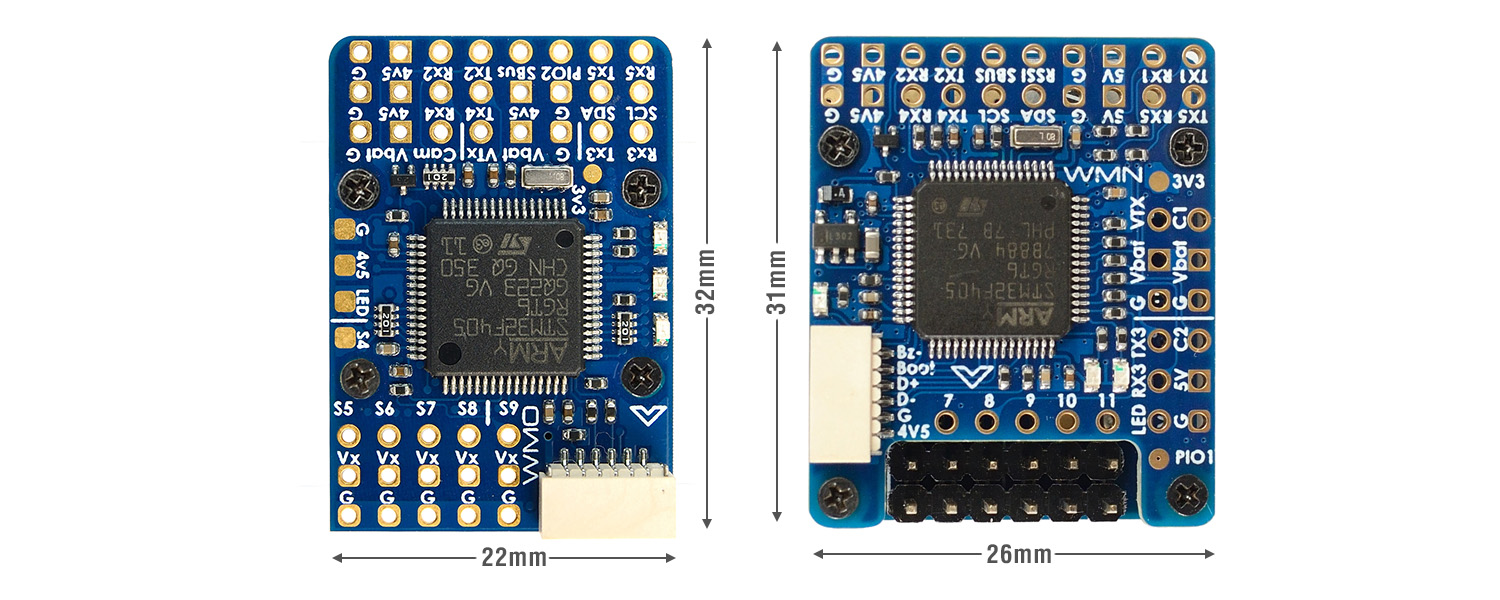
| F405-WMO | F405-WMN | |
| Size | 32* 22mm | 31*26mm |
| Input Voltage | 5.4 – 30V | 6 – 30V |
| PWM | 10 | 12 |
| UARTs | 4 | 5 |
| ADC | 2 | 3 |
| Regulators | 5V/2A & Vx/7A | 5V/1.5A & Vx/5A |
| Dual Camera input | No | Yes |
| Vbat Filtered | Yes | No |
| Vbat ON/OFF | Yes | No |
| Blackbox | SD card | 16M Flash |
| INAV | MatekF405TE_SD | MatekF405TE |
| ArduPilot | MatekF405-TE | MatekF405-TE |
Announcement
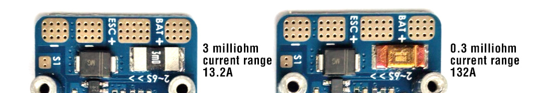
- Due to incorrect components of the shunt resistor were placed during the SMT process. The current sensor range of the F405-WMO has been changed to 13.2A (scale 2500). If the shunt resistor on your F405-WMO PDB is marked “3m0″(3 mΩ), please contact the dealer you originally purchased from to get a new PDB. We will gradually send out the new PDBs to resellers.
- The PDB equipped with 3 mΩ(mark 3m0) resistor can still be used on low-current(<15A) aircraft, with more accurate current measurement performance.
- Dec.22, 2025